Handlekurv


Handlekurven er tom

0,-

0

964/993 HVAC system details


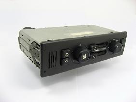
Climate Control Unit

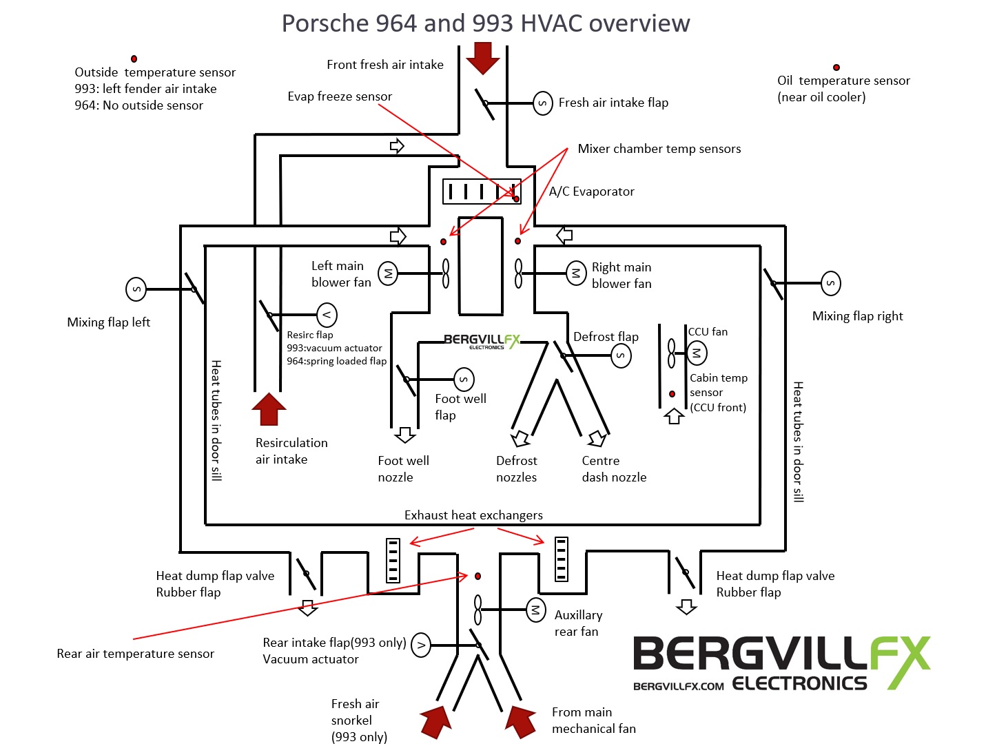
The Climate Control Unit (CCU) in the Porsche 964 and 993 has the following main functions:

  • Monitor the air temperature in the cabin by blowing air over a sensor in the CCU front panel (CCU fan)
  • Monitor the CCU fan operation
  • Monitor the ambient (outside) air temperature (993 only)
  • Monitor the oil temperature
  • Monitor any freezing of the A/C evaporator
  • Monitor both front fans and rear fan operation (fault detection)
  • Monitor the air temperature in the two front an mixer chambers (nozzle air temperature)
  • Monitor the engine temperature to be able to run the aux fan in cooling mode at ignition off if needed
  • Control the A/C condenser fan low speed setting. (high speed controlled by pressure switch)
  • Control the oil cooler fan in the right front fender (low and high speed)
  • Control the front interior fan speed (two fans, 4 steps using PHVAC system overviewWM)
  • Control the engine compartment (rear) cooling/hot air blower fan (low and high speed)
  • Control the amount of fresh air from the front air intake (servo motor)
  • Control the amount of heated air from the engine heat exchangers (two mixer servo motors, one for each side of the dashboard)
  • Control the amount of air to the defroster or centre nozzles (servo motor)
  • Control the amount of air to the foot well nozzles (servo motor)
  • Control the recirculation flap (993 only, a vacuum operated actuator)
  • Control the A/C compressor clutch mechanism
  • Monitor the gear shift, if reverse gear is selected, both mixer valves close to avoid exhaust fumes in the cabin
  • Activate the DME Coasting Shutoff function in the engine control unit
  • Log any faults detected in the systems and present them through the OBD interface

In addition to the above there is two pressure switches in the A/C refrigerant system that supervise the pressure and control the condenser fan and compressor operation.

CCU user controls

The CCU control layout depends on market and car options. RHD cars have the fan speed control at the left, LHD at the right. There are versions without A/C functions, and the 964 version have no A/C max button. It is perfectly possible to use the 993 part in the 964, but it requires modifications to the wiring loom. See the CCU page for details.

Temperature control
Control the air temperature in the cabin. This is done by opening and closing the mixer and fresh air servos.

Fan speed control
Control the speed of the two front fans, but also the speed of the rear blower depending if there is need for heated air or not. (temperature setting dependent)

Defrost switch
Shortcut button for max front and rear fan speed, defrost servo to windscreen only, foot well servo closed, A/C ON and max temperature. (mixer servos open, fresh air servo closed)

A/C switch (snowflake)
Enables the A/C compressor and the condenser fan to cool the incoming fresh (or recirculated cabin) air. Desired cabin temperature is set by the temperature control.

A/C max switch (large snowflake, 993 only)
Shortcut button for A/C compressor enable, max front fan speed, minimum temperature, mixer servos closed, fresh air servo closed, recirculation flap open, and no air to foot well and defrost nozzles (maximum cool air to the manually controlled air nozzles)

Recirculation switch
Fresh air servo close and the recirculation flap opens. This is a vacuum operated flap actuator in the 993 and spring loaded flap in the 964.

Defrost control (upper slider)
Selects air flow to the windscreen or to the dashboard vents.

Foot well control (lower slider)
Controls the opening and closing of the foot well flap.


CCU control mechanisms


Cabin air temperature
The cabin air temperature is constantly measured by a sensor in the CCU front and the desired temperature is set by the user. The temperature on the air coming out of the dashboard nozzles are controlled by adjusting the amount of fresh or A/C cooled air as well as heated air from the engine exhaust heat exchangers. The resulting air temperature is obtained by adjusting the opening of the fresh air flap and the two mixer flaps. The CCU fan motor operation is supervised and logged by the CCU. The CCU temperature sensor and fan must be clean and working, see chapter Air temperature decrease over time problem in our HVAC faults page.

A/C compressor operation
The CCU will activate the A/C compressor engage output if the following conditions are met:

  • -One or both A/C switches ON
  • -Fan speed setting above 0
  • -Evaporator sensor reading above 4°C
  • -Outside temp sensor reading above 4°C (993 only)
  • -Engine running
  • -Terminal X power feed OK (Term X must also been off during cranking)

The compressor mostly run in 10-30s intervals depending in 20°C ambient temp, and the condenser fan speed will depend on the need for cooling and ambient temperature. The clutch engage signal (active GND) is routed from the CCU through the three-level pressure sensor switch. (see below)

The Porsche 993 has an outside temperature sensor placed in the left front fender opening. If this sensor reads 4°C or below, the A/C compressor will not be engaged. This can also happen when the sensor is damaged. Use an OBD tool to read out any fault codes and/or the sensor actual value. All CCU models (except the first version of the 964 unit) also needs a fan setting above zero in order to engage the A/C compressor.

The GND engage signal from the CCU activate the compressor clutch relay placed in the engine compartment fuse box. The +12V feed to this relay come from the R01 Backup Light relay in the front fuse box.
If the relay does not activate as it should, pull it and check for GND on pin 85 and +12V on pin 86. If there is no GND on pin 85 you most probably have too low pressure in the system, and the CCU signal have been disconnected by the pressure switch. See below.

If there is no +12V at pin 86, first check the 7,5A fuse in the engine compartment fuse box. Then, check fuse 14 in the front fuse box. Pull relay R01, and check for +12V at terminal 87. The relay shall connect terminal 87 and 30 when activated, you could jump these with a short wire to find any relay failure.

CCU power supply and fuses

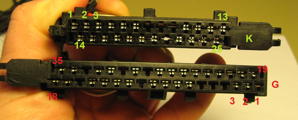
The CCU have several power supplies and fuses, these can be tested with a voltmeter on the CCU harness connectors:

  • Pin K1, GND
  • Pin K2, Terminal 30, permanent +12V, Fuse 1
  • Pin G17, Terminal 58d instrument lights, Fuse 36
  • Pin G29, Terminal X, switched +12V, Fuse 28
  • Pin G35, Terminal 15, switched +12V, Fuse 17

Three-level pressure switch
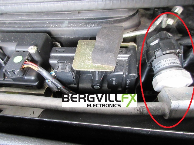
The switch really contain two switches. One of them cuts the CCU clutch signal and turns off the compressor if the pressure is too low, (2.5 bar) or too high (27 bar) in the A/C refrigerant circuit system. The other switch set the condenser cooling fan speed to high if the pressure exceeds 17.5 bar. The sensor assembly is mounted on the metal A/C pipe near the HVAC servo motors in the trunk.

Test the switch like this: Turn A/C ON (by pressing either of the buttons on the CCU) The GND signal shall be present on the sensor connector pin 4 (black wire). If pressure is OK the signal shall also be present on pin 1. (white/orange) You could also disconnect the sensor connector and use an ohmmeter to measure any connection between pin 1 and 4. The condenser cooling fan pressure switch has GND connected to pin 3 and closes to pin 2 (brown/black) if the pressure is over 17,5 bar.

DME Coasting Shutoff
The CCU is connected to the DME engine control unit, and this signal enable the CCU to stop the fuel supply being cut off on the overrun. This is only done when heat is needed in the cabin. (depending on the temp setting and ambient temperature) The idea is if your going down a long mountain road it keeps the engine temperature up so you still get heat from the heaters. This was one of the improvements Porsche implemented to get the heating system to work more effectively, as using the exhaust system as heat source in a air cooled engine.

Mixing chamber temperature sensors
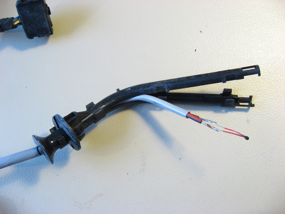
Each of the two mixing chambers have their own NTC thermistor sensor. These are made as a part of the car wiring harness. It is easy to change the 10k NTC sensor using a soldering iron.

A failing mixing chamber sensor can make the according mixer servo to behave strangely. As mentioned below, both mixer servos normally move simultaneously. A failed mixing sensor can make the servo to not be moving proportional to the CCU temp knob setting, but make it move between extreme positions only. The Porsche Service Manual mentions that a failed mixing chamber sensor will be automatically taken out of consideration by the CCU, but if the sensor is partly working it might create problems for the regulation mechanism.

Fan operation

There are a total of six fans (seven in a Turbo)

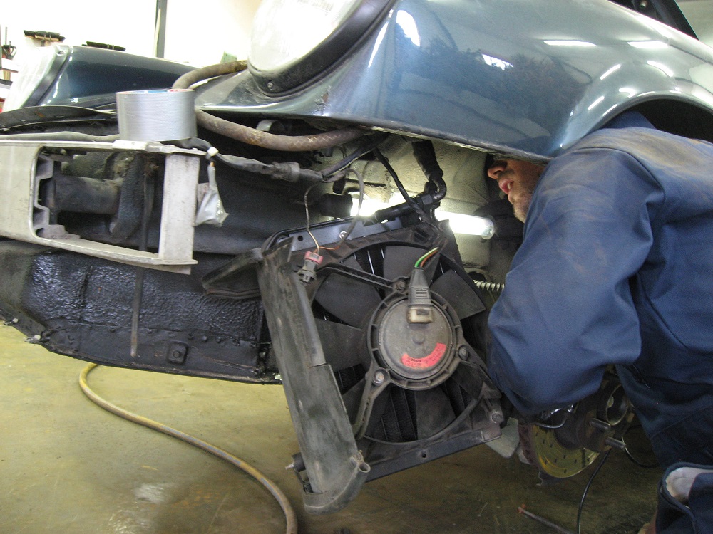
  • Condenser fan, in the front left fender
  • Oil cooler fan, in the front right fender
  • Left and right interior front fans, in the luggage compartment. Speed is controlled using the knob on the climate control unit (CCU).
  • CCU fan, a small fan mounted at the back of the CCU for measuring temperature. This fan is known to become noisy and fail over time. See our CCU details page for details on the CCU fan.
  • Rear fan (or aux.) blower, left side of the engine compartment. This supplies forced heat when running, also helps cool the engine under certain circumstances. The turbo have two rear blowers.

Condenser fan
The Three-level pressure switch set the condenser cooling fan speed to high if needed. See above. The condenser cooling fan run at high speed if fed with 12V, and low speed is obtained by switching a power resistor/ballast (0.45Ohm) in series with the fan motor. Relay R14 contain the two relays for fan speed change. This resistor is mounted on the condenser, and is known to fail due to overheating and corrosion. Always fix a broken ballast resistor on the condenser fan, you do not want excessive pressure in you A/C system, it can cause leaks!
Any refrigerant pressure faults will not be logged by the CCU since the pressure switches is directly connected to the compressor and condenser signals. The condenser blower motor operation is supervised and logged by the CCU. Air temperature at the centre dash nozzles shall be about 7-8degC with an ambient temperature about 20 degrees. Measure with A/C ON, resirculation ON and max fan. (or push the A/C max button on the 993)

Oil cooler fan
The CCU monitors the oil temperature and run the cooling fan in the right front wing at two speeds (off/low/high) to maintain correct oil temperature. Relay R04 contain the two relays for fan speed change. The oil cooler fan low speed resistor (0.45Ohm) has the same tendency to fail as in the A/C condenser fan assembly. See the A/C/Oil cooler fan DIY page for details. The oil cooler fan blower motor operation is supervised by the CCU.

Front interior fans
The front fans are placed in the back end of the luggage compartment, under the windshield beneath a black plastic tray. Fan speed is adjusted by the user and the operation is supervised by a feedback wire. The 964 CCU have a minumum fan speed of 1, despite the "0" fan speed setting on the knob. The 993 CCU allow fan speed from 0 to 4. The CCU use Pulse-Width-Modulation to control the fan speed in four steps, and this signal is wired to the high current driver Final Stage placed behind the fuse box. The CCU will sense a failing high current driver or fan motor and shut down the PWM signal. If the high current driver fails completely and short the transitorized output, the fan will run continuously. Pulling fuse 1 will stop the fans. The front fans will automatically be shut down if there is a fault in the rear AUX fan. See below for details. The right fan motor is Bosch# 0 130 063 023. Porsche part number are: left: 964 572 015 01, right: 964 572 016 01.

Rear (AUX) fan
The rear fan(s) has two purposes. (Turbo models have two rear fans) One is to help blowing air through the heat exchangers onward to the front fans torear_fan improve the heating of the cabin. The fan run at two speeds, and typically starts at mid temperature setting on the CCU. The fan will run on low speed if the fan speed knob on the CCU is below 2. Fan settings above 2 will set the rear fan speed to high. Remember, the operation of the fan is also dependent on the temperature setting, i.e. if it is set to minimum, the rear fan will not start since no heated air is needed to the cabin. However, on minimum temp setting, the fan could automatically be started by the cooling function, see below.

The second function of the rear fan is to do additional cooling of the heat exchangers/engine when in normal operation, (if temperature knob is set to minimum and mixer servo flaps are closed) and at ignition off by blowing the heated air out through two spring loaded dump valves under the engine. The mixer flaps closes to enable the fan to build up enough air pressure to open the dump valves.

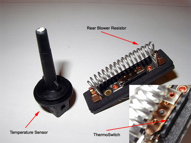
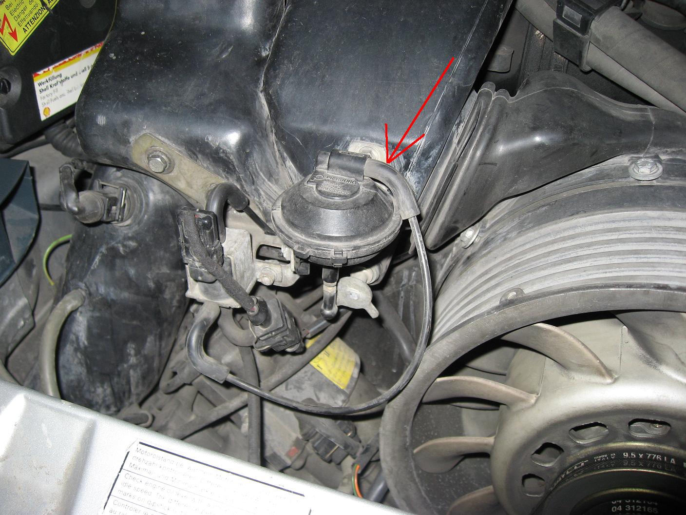
The CCU supervises the engine/air duct temperature with a temperature sensor, (see picture) and run the fan at low speed (40-45degC) and high(62-57degC) when ignition is ON and mixer valves are closed. (minimum heat setting) At igntion OFF, the fan run in low speed if the air duct temperature is above 75degC, and shall stop when below 70degC.

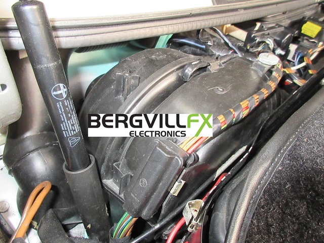
Fan speed is controlled by a relay in the left electronic unit in the engine compartment, (see picture) and low speed is done by switching a series resistor/ballast with the motor, similar to the oil cooler/A/C condenser fans, and uses the same relay type. The low speed resistor (#964 616 550 02) is mounted on the air duct beneath the fan housing for cooling, and it contains a thermoswitch for resistor overheat detection. This is done to protect the resistor and possible engine fire if the fan seizes or short-circuits. This thermoswitch can fail over time and disconnect the resistor, thus no low fan speed. There seem to be a method of resetting the thermoswitch, have a look at the pictures or on this thread on Rennlist. I always change a failed resistor.
The AUX/rear fan relay has been seen to fail due to excessive current, often caused by a seized or damaged fan motor. Test the relay by removing it and short terminals 30 and 87 to start the fan at high speed, and short terminals 30C and 87C for low fan speed. See the relay underside for terminal IDs. Test the CCU control signals to the relay by measuring on terminal 85 and 85C. These will be grounded by the CCU at high and low speed accordingly. (plus on terminal 86)

The CCU supervises the rear fan operation by a feedback signal. If the fan is seized, resistor is faulty or its fuse blown, the CCU will produce a OBD fault code, and stop the front fans intermittently if the temperature control is turned up and heated air is needed. The defroster fan operation will also cut out shortly after starting due to the max heat setting. CCU connector G19 and G1 are the blower motor supply voltage feedbacks. In case of using a "RS duct" modification and rear fan delete, you will have to fool the CCU into thinking that the fan motor is OK in order to avoid the front fans to shut down. The simplest method to do this is to connect switched +12V to the rear fan terminal 87. (the relay can of course be removed)
 

Rear fan run time
The maximum fan run time at ignition off can be up to 20 minutes. If the fan does not stop you might have a problem with the rear duct temperature sensor (CCU erroneously measure a too high temperature) or the fan speed relay may be burnt or damaged to stick in the ON position. The Porsche 993 has a vacuum operated air inlet actuator placed nearby the temp sensor, and the connector to this is similar to the temperature sensor. These can mistakenly be swapped, with the result of erroneous temp sensor readings.

Electric flap servo motors

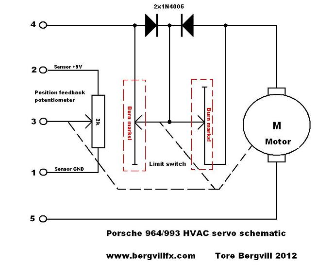
The air flow control flaps are operated by five electric servo mechanisms similar to common R/C servos used in remote controlled cars and airplanes. These consist of an electric motor with gear that runs in both directions controlled by the CCU. The servo mechanisms also contain a variable resistor (potentiometer) for position feedback to the CCU, enabling gradually movement of all servos, not just on or off.
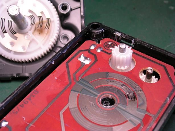
The servo also contains a rotating limit switch arrangement, made by printed tracks on the PCB, much like the potentiometer. The motor current runs through these tracks, and the switches cut the motor current if the maximum allowed travel is met.
The motors wear over time, and may develop a short circuit in the commutator. The printed limit switch tracks will then be damaged by the excessive motor current, and failing servos with burnt tracks and/or rotating contacts inside the servo is the second most common fault in the HVAC system in the 964 and 993. (No refrigerant is number one)
A fault in the limit switches could stop the servo from moving at any angle or position, and it could be revived for a short time by knocking it. This is of course not a long-term solution.
All the flap servo mechanisms are supervised and logged by the CCU. The servos are basically the same unit, but the travel angle (60° and 130°) and mechanical details as connecting arm and so on are unique for the different parts.

Five servos are controlling the air flow:
Mixer flaps. Two servos, one for each side, for the temperature mixing flaps that feed the mixing chambers. These servos are placed in the foot wells for a 993 and in the trunk in a 964. The mixer flaps will almost always move simultaneously. It can be a bit difficult to spot any servo flap movement; it is a fairly compact unit. Disconnect the air hose to see the flap inside. Here is a cached version of a Porsche 964 servo/HVAC page.
Foot Well flap. Controls the amount of air to the two foot well nozzles.
Front Fresh air intake flap. Controls the amount of outside air let into the HVAC system .
Defrost flap. Controls the amount of air going to the dashboard centre or windscreen vents. All servos are in the back end of the luggage compartment, under the windshield beneath a black plastic tray. (Except for the two mixer servos in the 993)

Servo part numbers

  • 964 Mixer servo: 964 624 324 00
  • 964 Foot Well servo: 964 624 903 00
  • 964/993 Defrost servo 964 624 902 00
  • 964/993 Fresh air servo: 964 624 901 00
  • 993 Mixer servo: 993 624 325 00
  • 993 Foot Well servo: 993 572 905 00

The CCU will shut down the servo as soon as the potentiometer feedback is not reported correctly according to any applied motor movement signals. The servo motors are controlled by output drivers in the CCU, and some have had problems with failing drivers as well the servo itself. A failing output driver will also stop any motion in a servo. See the CCU repair page for details on the drivers. 993 CCU units have an inbuilt test sequence program that makes it possible to move all servos and actuators. This is a convenient to detect any mechanical faults in flaps or connection rods. However, the CCU does not supervise the position feedback while moving the servos as in normal operation. This makes this an unsuitable test method for failing servos. You will have to use an OBD tool to activate the test program.

Testing a HVAC servo
The most reliable method of determine any printed track or rotating contacts damage is by popping open the servo and do a visual inspection. A failing motor is difficult to see, and the motors are very difficult to open. You could try to apply 12V to the motor and may be able to discover abnormal currect draw, but it may work OK for the moment. The potentiometer resistance can be tested by applying 12V to the motor and measure the resistance of the pot while the servo is moving. However, the result could be unreliable if the potentiometer and rotating limit switch tracks are damaged. It would appear working OK at some points of the travel, and not on others. Whacking the unit has been mentioned to "fix" this, but that would be at best a temporary solution.
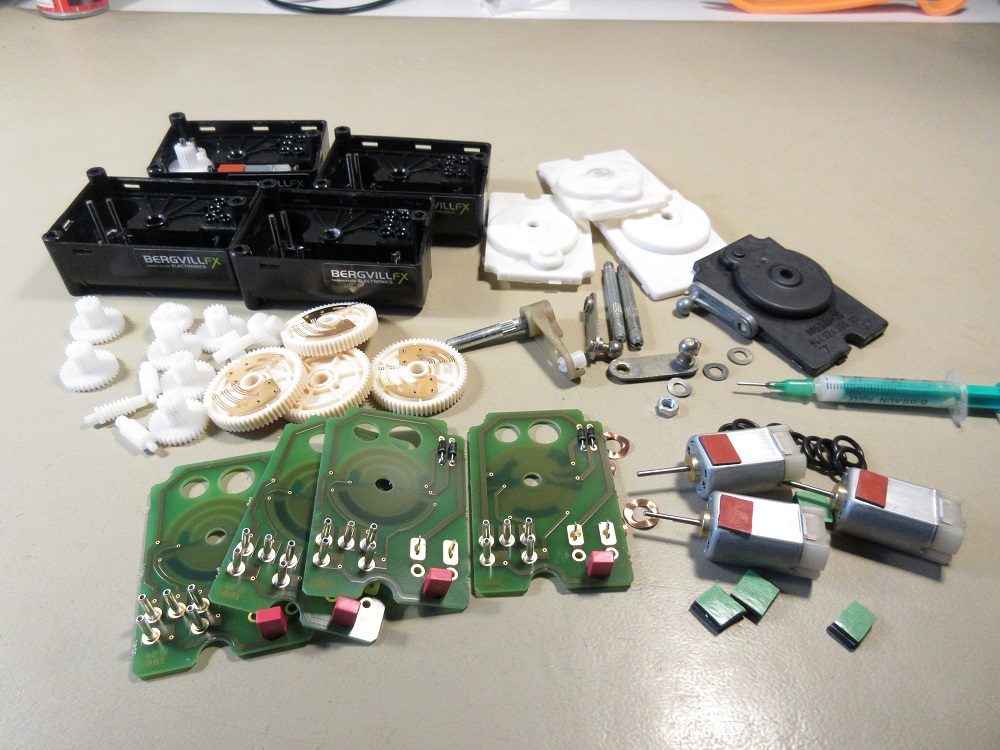
The bottom line: If you see any damage to the rotating slider contacts or printed tracks, change the servo into a new spare part or a refurbished unit. PARTisan Autoteile has a refurbish service.


Flap movement overview
Temperature set to minimum: Fresh air servo open, both mixer servos closed, resirc flap closed (993 only)
Temperature set to maximum: Fresh air intake closed, both mixer servos open
Reverse gear: Both mixer servos closed to avoid exhaust fumes in the cabin. (993: the reverse air intake switch also change to fresh air position) Ignition off: Fresh air and mixer servos closed, CCU fan run for 5-15 minutes after ignition off.


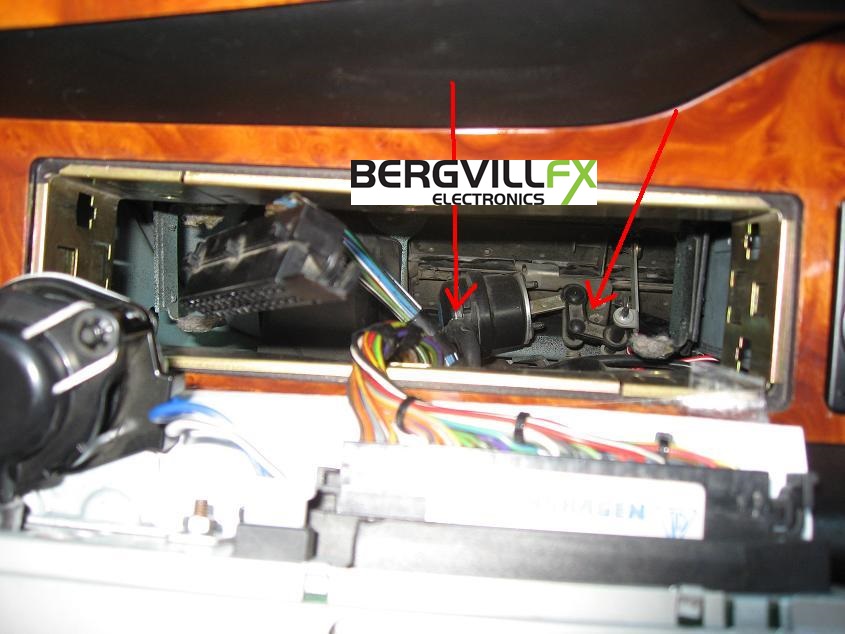
Vacuum operated resirculation flap

In the Porsche 993 the CCU controls the operation of a vacuum actuator-operated recirculation flap in the dashboard behind the CCU. The 964 has a spring-loaded flap with no actuator, opening by air vacuum caused by the fans when other flaps are closed. The resirc flap will close at minimum temperature setting (993 only) when A/C is on to enhance the cooling effect.

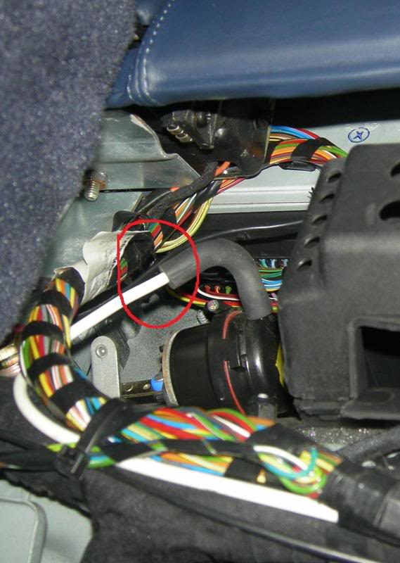
The resirc actuator can also be seen from underneath the dashboard, but it is clearly visible through the CCU opening in the dash. The vacuum hose is connected to the actuator by a 90 degree rubber hose.
The electric valve that open and close the actuator is placed in the trunk near the air flow servos. The same problem occurs here, disconnected hoses make the recirculation flap unable to operate. You can suck on the vacuum line going from the valve to the actuator to test for mechanical operation of the flap. The vacuum hose from the engine is routed along with the electric wire bundle through the cabin. An electric fire in the bundle due to a short circuit may damage the hose.
A vacuum leak can cause the flap to be flabby and close with a "whoompf" sound when the engine is revving and vacuum is reduced. This especially occur with CCU fans on maximum setting creating a slight vacuum in the mixing chambers, sucking the flabby recirculation flap to closed position.
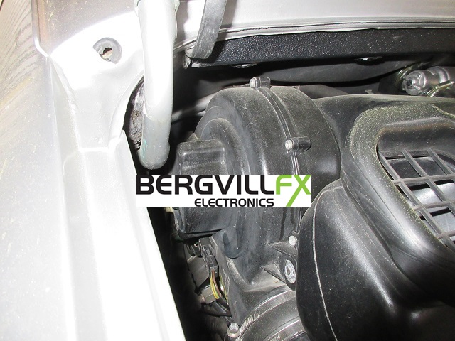
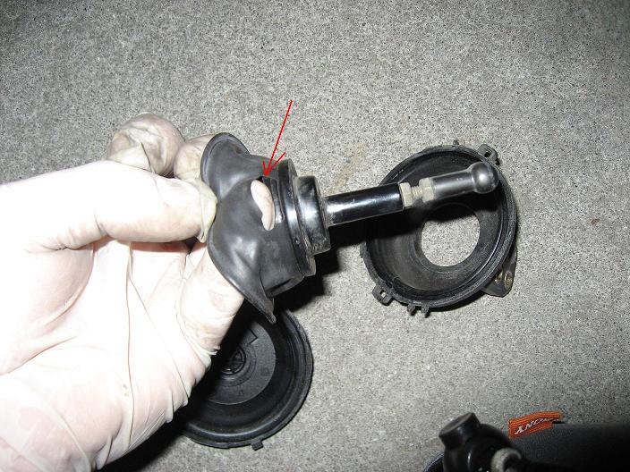
Finding vacuum leaks can be difficult, but are often caused by disconnected lines or failed actuators. Check that all rubber hoses are connected on both actuator in the dash and valve in the luggage compartment. Faulty vacuum lines and components in the engine compartment can also be the culprit for leaks. See the picture for an example, a damaged vacuum diaphragm on the air inlet actuator in the engine compartment.
Porsche993_Vacuum_schematics