The shopping cart is empty
Menu
- HID/LED lamps
- OBD diagnostics
- T-LOCK keyless entry
- Car audio
- Pad/Switch Keeper
- Spare parts
- Downloads
- DIY section
- Cayenne 958 drain pipes
- 964/993 HVAC fault overview
- 964/993 HVAC test procedure
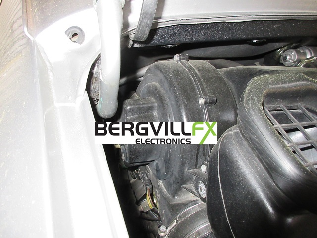
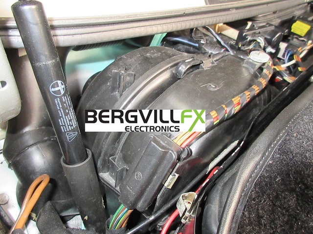
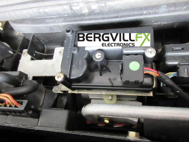
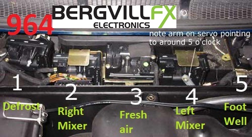
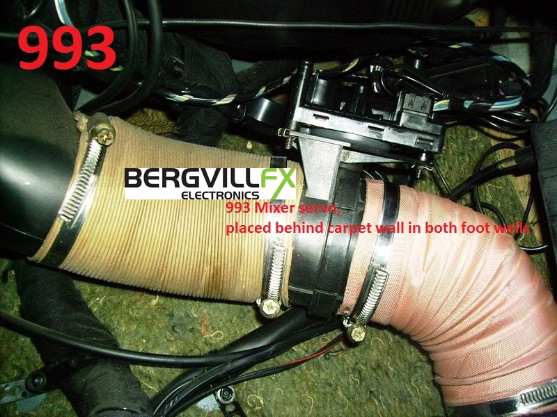
- 964/993 HVAC system details
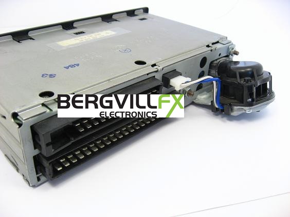
- 964/993 CCU details
- 964/993 A/C- oil cooling fans
- 964/993 Centre Console lights
- 911/964/993 OBC Tachometer
- 964/993 Rear spoiler wall
- 964/993 Rear spoiler mechanism
- 964/993 Current measurement
- Gas strut change
- Service portfolio